Unfortunately, because of time constraints and the rapid nature of my senior year I haven't been able to keep up with my blog posts. At this point in time the project has concluded and I will be presenting in about a week to specialist and employees at -. -. ---- and ---------.
During this project I fell short in how much I was able to accomplish during my time at ------. I fell short in that I wasn't able to design conduits and work fast enough to get them all tested. In the end though, we did test several different models which yielded great results and I did prove that it is indeed possible to create a bench top model of an aortic root to assess paravalvular leakage.
While I was here I gained actual technical skills in CAD modeling and the maintenance of a left heart simulator. But all of this technical experience amounts to nothing when compared to how much my advisors taught me. My advisors didn't just teach me skills but they showed me qualities that I lacked and need to gain in order to excel in the workplace. I now see how important it is to "measure twice and cut once," or that is no excuse to arrive late or provide mediocre work. While working with my advisors I have learned the importance of communication between members on a team. And no matter how much you believe that you can accomplish a task on your own, that it is necessary to humble yourself and ask for assistance. I have learned more than I could have ever expected from my senior research project.
Honestly, at the beginning of this project I was terrified by what was going to come. The objectives that ---- H , and ---- M, set for me seemed daunting. But I did it. We didn't finish everything but we accomplished a ton. And from the process I learned: to not be afraid of failing, no matter how big the task may be. Because even if you do fail or fall short, you will learn things along the way that set up a foundation for the future.
Thank you for teaching me that C--- H------, and D---- M-----.
This is my final signing off. Hope you guys learned something from my earlier posts!!!
Thursday, April 30, 2015
Tuesday, March 31, 2015
Print Success
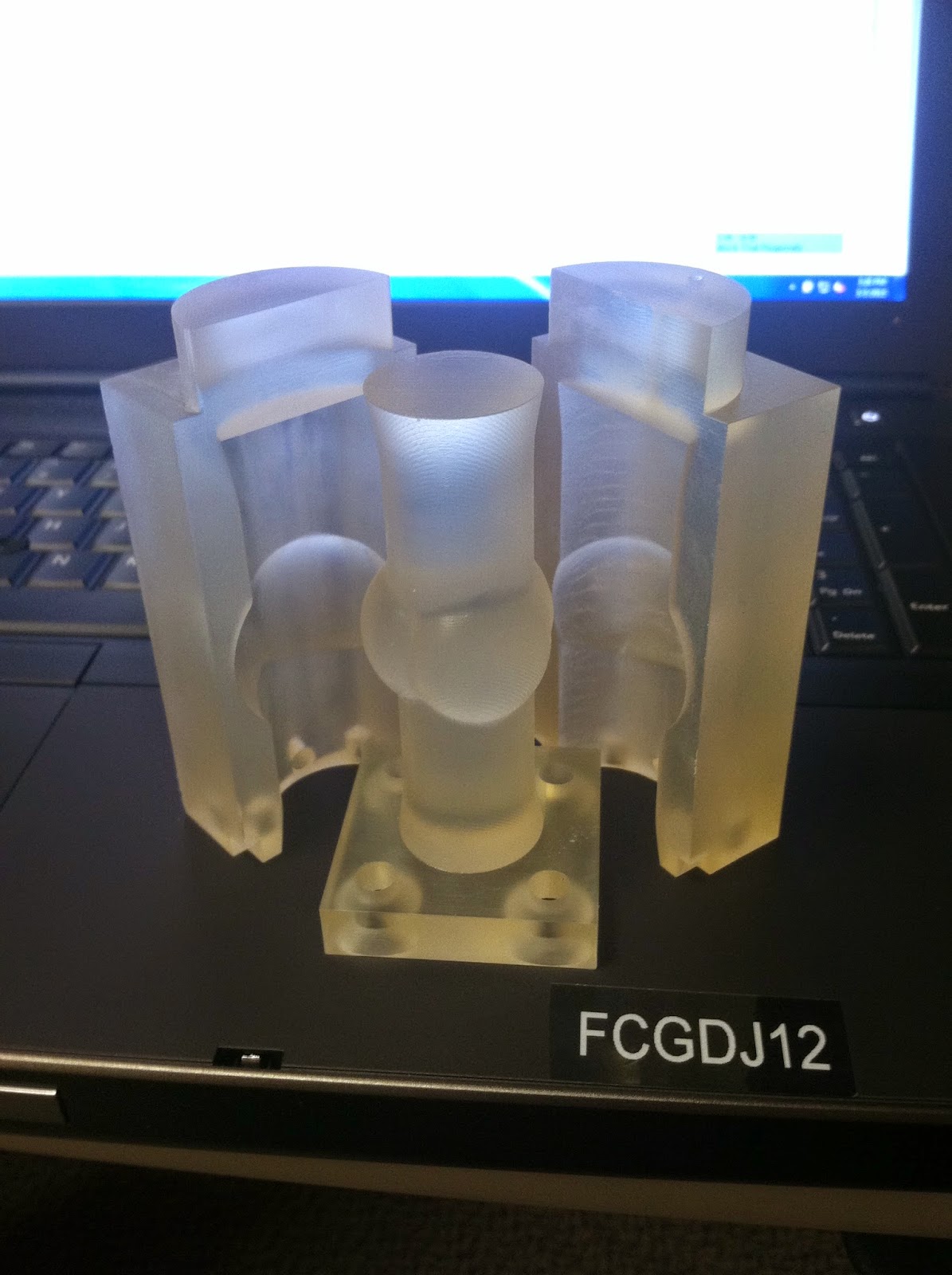 |
| Figure1 My SLA Printed mold! |
The first step in processing before we can inject is the sanding. I just used a Dremmel tool for this step and fine waterproof sandpaper. Though SLA printing is extremely accurate and the mold came out fairly concentric, I need to smoothen the walls. If the mold surface is too rough then the silicone might bind to the surface of the mold and make it difficult to de-mold or tear when separated. Additionally, the silicone tube will have clarity issues and will be difficult to see through.
 |
| Figure 2 |
The second step involves a chemical bath in isopropyl alcohol (IPA bath). This step will remove all the excess wax left on the mold and clean the surface of it.
Then the final step includes hole tapping. This is where I make the threads inside the holes on the bottom of the mold. I am going to do this so that the mold can be fastened together for the injection via screws.
**Hindsight note. After completing the processes above, I would recommend doing the bath before the sanding. After the IPA bath the mold was coated in a material that I ended up having to sand off. So to save time, give the mold the bath first**
 |
| Figure 3 Hole tapping |
Thank you for taking the time to read through one of my posts. Please comment if you have any questions or just want to be heard. I look forward to responding.
Monday, March 23, 2015
SLA Print Fail......
Hi there readers! So I finished my designs on SolidWorks, got them approved by my advisors and submitted them to be printed. There's just one problem: the format the file was sent in. Sadly, my first SLA print was a failure and that "three piece mold" I am going for was printed as a single block of 3d printing resin filled with wax. Unfortunately this puts me back a couple of days, but I now take my advisors words to heart, "Measure twice, cut once." So now I am stuck with a pretty cool looking paper weight (see figure 1). But I thought that I would take some time to talk about how the SLA (Stereolithography) or 3D printing process works.
First and foremost, 3D printing or stareolithography is an additive manufacturing process used to construct prototypes, patterns and molds. A photo-reactive resin is repeatedly "printed" and then cured using a ultraviolet laser. It is an emerging technology that was first used in 1986 by a Charles Hull, but it hasn't been widely used until the last decade. One of the advantages of SLA printing is how quickly a part can be processed. Though it depends on the size of the part, a machine ready part can be printed in downwards of half a day. SLA printed parts can be used as prototypes or as machine ready parts in injection molding, thermoforming, blow molding and some types of metal castings. This technology is cutting down processing time for manufacturing companies around the world, if they can afford the startup cost.
Though there are many benefits and applications of SLA printing, it costs an arm and a leg to buy the printer. Industrial processing quality printers range from $100,000 to $1,000,000 depending on their printing envelope (how big of parts they can print). Additionally, the UV curing resin that the printers use costs about $210 a liter. If a company wants to print anything larger than 1m x 1m they are looking at the price of printers going up astronomically. So the technology is great for specific application and it can cut corners in manufacturing, but one has to weigh in how much it actually costs to use.
In terms of how it all works, the process is fairly simple. A single platform is suspended in a pool of a liquid polymer (UV Photo-sensitive resin) and then a laser is manipulated via reflecting mirror to create the first "layer" of the shape you wish to construct. The mirror reflects the laser into the liquid resin and it cures as a solid, the platform then lowers itself so now the solid it created is just below the surface of the liquid polymer. The laser again draws the next programmed shape on the liquid and it cures as another layer of solid resign while sticking to the top of the first layer. The platform then lowers itself and the process repeats.
For a better visual and understanding of what I attempted to explain above, see the video attached bellow. They explain it much more "solidly."
 |
| Figure 1 |
 |
| Figure 2 SLA printed heart model (Right)/ Actual heart (left) |
 |
| Figure 3 Machine Ready SLA print |
 |
| Figure 4 SLA Printer |
For a better visual and understanding of what I attempted to explain above, see the video attached bellow. They explain it much more "solidly."
Thank you for taking the time to read through one of my posts. Please comment if you have any questions or just want to be heard. I look forward to responding.Monday, March 9, 2015
CAD Modeling Experiences
I have now waded through the complicated stages of CAD design... it was more complicated than I had anticipated. But I am extremely satisfied with my results. I began this stage by simply taking tutorials on SolidWorks to get my bearings but I wasn't learning how to do things fast enough or specific enough to my project design. Consequently, I just dove in and started designing by myself and got lost. If it wasn't for the guidance of my advisors I wouldn't have gotten very far. I don't mean to sound like a grammy acceptance speech but before I talk anymore about CAD design I need to thank -------, ---------, ---------, and ----------- and YouTube for all of guidance because without them I would have been completely lost.
 |
| Figure 1 Mano Thrubrikar's Valve Design Sketch |
 |
| Figure 2 Annulus sketch |
 |
| Figure 3 Mock Annulus |
 |
| Figure 4 Mold of Annulus |
With the mold design that I have made I will be able to go back and make adjustments if necessary. But at this point in time I have the green light approval from my advisors, so I am off to the 3D printer! So far this point in the project has been my favorite. My advisors have truly shown me what it is like to be an engineer and take an idea and turn it into a physical representation.
And who knows? If I have the time, I might even build a three dimensional model of BASIS Flagstaff on Solid works. Yeah, you can do that.
Thank you for taking the time to read through one of my posts. Please comment if you have any questions or just want to be heard. I look forward to responding.
Tuesday, March 3, 2015
Proposed Methodology
After my initial literature review, I have learned tons about the anatomy and physiology of the aortic semilunar valve. But this has also made me realize how much there is to learn in this field. But with what I have learned and the guidance of my advisors I am confident in laying out the methodology for my research project. Though I anticipate changes, the project will be broken up into these key stages:
- Literature review of the aortic valve and transcatheter aortic valve repair and design of a aortic root
I feel like my foundation is strong enough move forward in my project, but I will continue my lit. review for the duration of the project. Currently I am in stage two of my project. This involves a theoretic design of the aortic root which I will later make out of silicone. I have decided to base my design of the aortic root off the design Mano Thrubrikar. This is an aortic valve design that is somewhat idealized and you would never see an aortic root this perfect in a living person, but it is a great baseline to work off of and adjust. For a visual, see figure 1. Once I have completed the theoretical design stage I can move into the computer aided design stage.
2. Converting this design into a computer generated model.
2. Converting this design into a computer generated model.
For the computer aided design (CAD) stage, I will use the program SolidWorks to create an anatomical representation of a mock aortic root. It will be approximately 45mm long with an inner diameter of 21.9mm and a wall thickness of 2.4mm. See bellow to see how this program works.
3. Creating a mold for this model
4. Casting silicone versions of aortic root with the mold
The next stage is self-explanitory in that we will inject some sort of platinum cure silicone into the mold. In order to fully cure the silicone it will need to be placed in an oven for an extended period of time at around 75 degrees Celsius.
5. Conditioning the silicone aortic root
After the annulus has been fully designed, injected and cured, I need to condition it. Because right now it is perfectly round and I realized. Due to the difficult nature of constructing them, leaflets were not added to this model. So the question is: how do I simulate calcification on leaflets without leaflets? And to answer that question: I don't know exactly. What is most likely to happen is, the volume occupied by the leaflets when they are open will have to be measured on a calcified valve, then on the CAD program this will be adapted to the aortic root design. So instead of creating of leaflets we will fill in the space that they would occupy with silicone.
6. Deployment of TAVI device into the silicone aortic root
At this point in the project we will actually deploy a TAVI device into the silicone aortic root. This will simulate a valve repair procedure in an individual with . The device that we will be testing is the Medtronic CoreValve. This device is a self-expanding (No balloon required to deploy it) nitinol frame heart valve. It is one of the most commonly used devices in TAVI procedures. The problem that I see arising with this stage is deploying the device correctly. There is a small "landing zone" that this device must sit in to correctly seal, as a consequence the accuracy of the data we collect is dependent on the deployment. Furthermore, we are deploying into a "mock root." Even though the silicone root was modeled after the real anatomical geometry of a person, it will have some inaccuracies.


3. Creating a mold for this model
After the model was made on SolidWorks I then have to convert it into a mold so that we can actually cast the model annulus. This should be fairly simple, but I will need to add in some sort of tapered holes so that the mold can be screwed together. From what I understand it will be a three piece mold. There will be an inner core and two outer faces. Each face will cover up the core and there will be a small space left in-between the core and faces. Once the silicone is injected it will occupy this space.
4. Casting silicone versions of aortic root with the mold
The next stage is self-explanitory in that we will inject some sort of platinum cure silicone into the mold. In order to fully cure the silicone it will need to be placed in an oven for an extended period of time at around 75 degrees Celsius.
5. Conditioning the silicone aortic root
After the annulus has been fully designed, injected and cured, I need to condition it. Because right now it is perfectly round and I realized. Due to the difficult nature of constructing them, leaflets were not added to this model. So the question is: how do I simulate calcification on leaflets without leaflets? And to answer that question: I don't know exactly. What is most likely to happen is, the volume occupied by the leaflets when they are open will have to be measured on a calcified valve, then on the CAD program this will be adapted to the aortic root design. So instead of creating of leaflets we will fill in the space that they would occupy with silicone.
6. Deployment of TAVI device into the silicone aortic root
At this point in the project we will actually deploy a TAVI device into the silicone aortic root. This will simulate a valve repair procedure in an individual with . The device that we will be testing is the Medtronic CoreValve. This device is a self-expanding (No balloon required to deploy it) nitinol frame heart valve. It is one of the most commonly used devices in TAVI procedures. The problem that I see arising with this stage is deploying the device correctly. There is a small "landing zone" that this device must sit in to correctly seal, as a consequence the accuracy of the data we collect is dependent on the deployment. Furthermore, we are deploying into a "mock root." Even though the silicone root was modeled after the real anatomical geometry of a person, it will have some inaccuracies.
7. Data collection with left heart simulator
Once the space between the device and the mock root has been sealed to the best of our ability, we test. The silicone root and device will be fastened into the Vivitro Pulse Duplicator system. This machine will simulate all the hydrodynamic conditions within the left side of the heart that the device will be exposed to while simultaneously collect the data on the volumetric flow of fluid through the device and the regurgitation infraction. This machine will show how much fluid is leaking through the device.
8. Leakage quantification through echocardiography
To further verify the data collected, additional testing needs to occur. In order to effectively see where the leakage is occurring, an echocardiographic machine needs to be used. This machine uses the Doppler Effect to analyze fluid velocities throughout the entire device. With this machine will be looking around the seal of the device for anomalies in fluid velocity. Where there are anomalies, there is a high possibility that there is a leak.
9.Analysis of data
Once the data has been collected, it will need to be analyzed and categorized. I hope to compare the amount of leakage between each of our test trials and clinical cases of paravalvular leakage. If I can show that the leakage occurred in same amount and in the same place as patient data, then I will have demonstrated that you CAN effectively replicate paravalular leaks in a lab setting.
10. Development and beyond!
Assuming that I prove my hypothesis, the test method that was created in the SRP can be used for further research. Researchers could potentially use this test method to quantify leakage in different brands and types of TAVI when compared to each other, or use the test method to develop treatments for leakage in a TAVI device. This SRP could be the step towards the next development in the field of transcathter valve repair or it could just demonstrate how not to build a mock aortic root. Well, I guess only time and hydrodynamic laws will tell.
Thank you for taking the time to read through one of my posts. Please comment if you have any questions or just want to be heard. I look forward to responding.
Monday, February 23, 2015
TAVI Foundation
Hello and welcome to all! I am very excited to have the opportunity to share what I will be researching over the next few months.
My senior research project is focused on the implications of Transcatheter Aortic Valve Implantation (TAVI) and potential problems that arise from this procedure. As an introduction to my research project I will lay some foundation on he application of TAVI.
| Figure 1 |
 |
| Figure 2 |
This procedure can be pro formed using a few different strategies. A physician can enter through the femoral artery (a large artery in the groin region) and access the heart by navigating up through the body's arterial system. This is called the transfemoral approach, which does not require a surgical incision in the chest. The second requires a minimally invasive surgical approach with a small incision in the chest and entering through the tip of the left ventricle or the apex of the heart. This is known as the transapical approach. For a visual, see figure 3.
| Figure 3 |
Thank you for taking the time to read through one of my posts. Please comment if you have any questions or just want to be heard. I look forward to responding.
Saturday, February 21, 2015
What is this?
Hi there, my name is Chance Marostica. I am a senior at BASIS Flagstaff and for my final trimester at BASIS I have been given the oppurtunity to participate in a Senior Research Project--SRP for short. My project will last a total of ten weeks, where I will be conducting research in a field of my choosing under the guidance of experts in that field. For the duration of the project I will posting on this blog to share and reflect upon my findings.
I have always wanted to conduct meaningful research and gain hands on experience in the real world, and thankfully I received that opportunity. A technology-based manufacturing company, ------------ graciously allowed me to participate in research! Under the guidance and mentorship of my SRP advisors, ------------ and -------------, I will be learning and researching the application of engineering in a research environment.
For my SRP I will analyze the implications of Transcatheter Aortic Valve Implantion (TAVI) devices. TAVI is still considered a realatively new procedure but research and development has resulted in the application and success of this procedure to increase greatly in the past decacde. Advancements include: more accurate analysis of diacom data, refined usage of arterial mapping, improvement in delivery devices, and variation in the design of prosthetic valve types. The credit for the vast majority of these advancements goes to private medical device companies and their drive to improve and extend the legnth of pateint life. Truthfully, this is what makes this research so meaningful to me. Maybe someday, the findings will be a small part of innovation in the medical field. Innovation that could improve a life.
Thank you for taking the time to read through one of my posts. Please comment if you have any questions or just want to be heard. I look forward to responding.
Thank you for taking the time to read through one of my posts. Please comment if you have any questions or just want to be heard. I look forward to responding.
Subscribe to:
Posts (Atom)